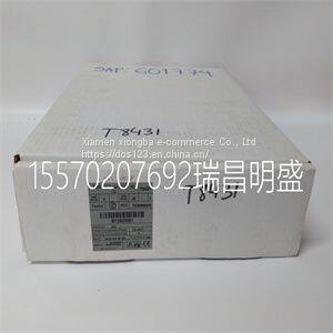
Module spare parts T8431
Product Details
Product Details
Product Description
Product DescriptionFocus on DCS, PLC, robot control system and large servo system.
Main products: various modules / cards, controllers, touch screens, servo drivers.
Advantages: supply of imported original products, professional production parts,
Fast delivery, accurate delivery time,
The main brands include ABB Bailey, Ge / fuanc, Foxboro, Invensys Triconex, Bently, A-B Rockwell, Emerson, ovation, Motorola, xyvom, Honeywell, Rexroth, KUKA, Ni, Deif, Yokogawa, Woodward, Ryan, Schneider, Yaskawa, Moog, prosoft and other brands
| T8431 |
>> Advanced Water Quality Analyzer, Cod Online Monitoring, High Precision, China Made Conductivity Meter
>> Factory new production biomass briquette press machine biomass coal press briquette machine for sawdust dryer
>> Ketchup Cooker Chocolate Sauce Mayonnaise Maker
>> 4K 4G Wireless WiFi Solar PTZ Dual Lens Outdoor Surveillance Video Digital Security Hikvision Drone Mini Spy Hidden IP Night Vision Wholesale Small CCTV Camera
>> Rubber Product Making Machinery 1/8-1.1/2′′ 6-38mm Hydraulic Hose Pressing Machine AC Crimping Tool Price
>> Factory Customized Advanced Sony Imx415 8MP 4K Ultra HD Super Definition&High Frame Rate USB Camera Module
>> Winter Autumn Orthopedic Shoes for Kids with Orthotic Insole
>> Best Shipping Agent Service to Thailand
>> IP65waterproof LED Split Solar Street Light with Remote Control Solar Street Light High Lumen for Road Application
>> Educational Training Equipment Flat Panel Smart Interactive Whiteboard
>> Carp Bait Lure Sea OEM Wholesale High Carbon Steel Cheap Fishing Hook
>> GAPV High Quality Hot selling Auto Parts Engine Cover For Crown GRS182 OEM 51410-0N010 2005- Year
>> Fakra z type to sma female for rg174 rg316 coaxial cable 0.5m
>> Horizontal Tank Septic Tank High Standard Blow Molding Machine Auto Production Long Lifetime
>> Diesel Engine Animal Food Feed Pellet Making Processing Pelletizer Fish Dog Feed Granulation Production Machine
>> high quality environmental protection wholesale food grade stand up kraft paper granola bag with zipper and clear window
>> Palm Shell Kernel Separator Gravity Destoner
>> Full Automatic Paper Napkin Machine for 1/2/3/4/5 Plys Embossing Napkin Paper
>> Auto Body Parts Door Lock Button Frame for Defender 90 110 130
>> Hot Cheap China New Machinery 18ton High Quality Wheeled Excavator
>> Strong Double-Sided Acrylic Adhesive Tape Waterproof Removable Residue-Free Strong Mounting Acrylic Tape for Car, Motorcycle, Home, Wall Mount, Photo Mounting
>> Disposable Restaurant Take Away Food Container Cornstarch Square Lunch Box
>> Agriculture Poultry Manure Processing Machine Animal Dung Dewater Machine
>> 1080P 30fps WiFi Mini Portable Action Dash Cam
>> 2021 hot selling high quality brake pads for byd s6 no asbestos no dust long life
>> Nanyang Mf115 Wood Saw Blade Grinding Machine Manufacturing φ 127× 22.2mm Emerald Wheel Specifications Band Saw Blade Sharpening Machine
>> small scale Ball Mill For Grinding Gold Ore Rock Grinding ball Ball Machine
>> Korea Caratfill 5.2ml*10 Collagen Stimulator Skinbooster Hyaluronic Acid Pn+Ha Healoine Dermal Injection Filler
>> Customize Logo School Backpack Cute Children Boy Girls Waterproof Nylon Backpack School Bag
>> 9-0753S Timing Chain Kit for SAAB A28NER with OE 12616608 12616609 TK5420